There is never enough being said about Industrial Engineering (IE), especially in the garment manufacturing domain. There are conceptions and misconceptions, there are viewpoints and sideline views, there are promoters and detractors, but Industrial Engineering (IE) is like a wholesome drink for the much sought-after balanced growth of any garment manufacturer. Before starting a new series, addressing this most relevant issue in a more organized manner, it is equally important to revisit the articles published in StitchWorld on the subject during the last decade. While the new series can be a ready reckoner for the industry, this is an awakener to realize your own strength and potential area that needs to be addressed. All articles have issue dates mentioned against them, so that those interested to read the detailed article can do so…
Methods Improvements Through Workplace Engineering
Paul Collyer StitchWorld March 2008
Sewing workplace can be defined as sewing machine, material input and output bin, operator seating area and the horizontal and vertical space in-between. Workplace engineering involves scientific placement of man, material and machine to facilitate easy and quick execution of the operation. Not only the big manufacturers with huge resources, but even the smaller manufacturers with limited resources can utilize the basic principles of movement and with little imagination make significant reduction in garment work content at minimal cost. Given below are key principles of method improvement:
• The component must be stored as close to the needle point as possible ensuring that it does not interfere with the sewing operation.
• It should be stored in a position so that it can be presented to the needlepoint ready to travel in the direction required, i.e. it does not need to be turned through 90 degrees or more.
• Where more than one component is involved, then wherever possible the operator should be able to pick them up simultaneously.
• Wherever possible, the operator should be able to grasp and release a component by only moving his arm from the elbow joint or failing that by engaging his whole arm from the shoulder and not having to move his upper body.
• Components should be stored in or as near to the same plane as the machine table.
• In practice, however, whatever the operation, many operators tend to store components:
a) On their knees – usually because they do not have the facility to keep them anywhere else or through habit. It is therefore necessary to lift the work to the level of the machine bench. As fabric is not rigid, when a piece is lifted it goes ‘out of control’ and requires extra handling to position it again.
b) On tables or upturned boxes, to the right of the machine. It is not possible to load components to the machine foot from the right. Therefore, the operator has to bring work to the entire length of the machine, transfer it to the left hand and re-grasp it before presenting it to the needlepoint.
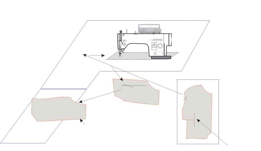
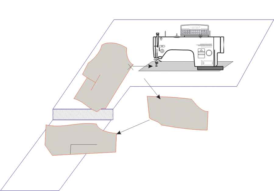
Examples of how to use low cost improvements in an existing machine layout for sew dart/front seam in jacket front are shown in Figure 1 and Figure 2.
The operator picks up with right hand at point indicated X. Note that it is grasped on the edge but not at the point to be placed under the machine foot, thereby necessitating a reposition and re-grasp. In this operation the fronts (in pairs) are on a table to the operator’s right. The movement sequence includes:
• Move the panel across the body, turning to right side.
• Reposition on bench.
• Align dart edges.
• Move to machine foot.
• Back tack and sew dart in one burst of sewing, auto cut threads.
• Dispose of by sliding onto knees.
• Move 8 -10 fronts to storage on left.
Of the cycle time of 0.095 minute, the dispose of/load was taking 0.046 minute. The existing layout breaks the ‘rules’ as panels have to be moved across the body and up a different level panel. Additionally the panel has to be moved through 90 degrees twice as it cannot be moved across the body in any other manner. By changing the workstation layout to Figure 2, the dispose of/load time is reduced to 0.027minutes, a reduction of 41.3% and 20% on the overall cycle time. In this layout the operator collects from the machine table to the left (with extension) and can therefore pick up on the same plane, work on the garment and then dispose of to his knees as before. Usually work would be stacked nearer to the machine foot but in this instance, as the fronts are laid in pairs, it is necessary to give sufficient space for every other one to be turned through 180 degrees. The only additional cost in this case is a small melamine extension to the table.
Methods Standardization Critical to Efficient Sewing and Cutting Section
 Reema Agarwal StitchWorld March 2003
Today the use of PMTS systems is rampant; however the real benefit of using PMTS in sewing floor is still elusive. More often than not, more than one method of handling the materials, presenting the components to the machine foot, pivoting, re-grasping, aligning and folding are possible and PMTS is a tool to standardise the methods. If the exact method is not explained in the PMTS and if the same method is not explained to the operator, there can be variations in methods. And slight variations in the method could lead to variations in time taken to perform the operations such as line balancing, piece rate calculation, target setting and productivity calculation. In such cases, the whole purpose of standardization of methods using this modern technique thus gets lost.
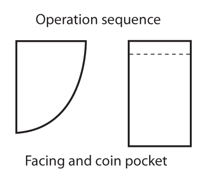
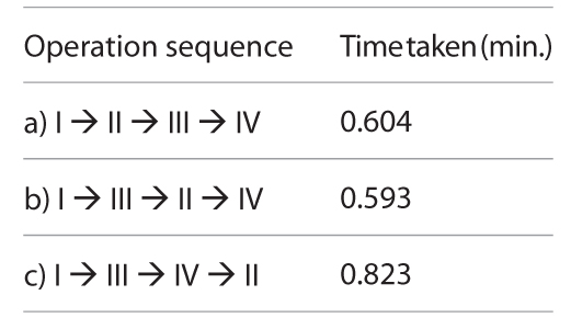
 A simple sewing operation of attaching coin pocket to the facing in a denim trouser requires a facing and coin pocket (pre-hemmed).
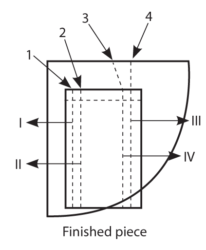
In this case, we can start either at point 1 or at point 2. If we start at point 1, the stitches I can be followed either by stitch II or by stitch III. And accordingly we have three different operation sequences possible and their respective cycle times are:
Thus, it is clear from the above example that one simple motion analysis can have more than one possible motion sequence, each of which may have different cycle time. So in order to maintain the essence of the sophisticated PMTS and derive the desired results out of it, it is very necessary to ensure standardization of methods by explaining the method step by step which is to be strictly followed by the operators without any deviation.
 While GSD is well known PMTS for standardization of methods in sewing room, its lesser known cousin GCD (General Cutting Data) does the same for spreading and cutting operations. The “Matrix” within GCD uses a base operation analysis and re-calculates the standard time for similar operations using the variables of lay length and depth. Increments for lay length and depth are simply entered by the user and the calculation process initiated. From any GCD operation, standards time can be produced for the given variables, thereby eliminating the need to measure and produce individual time standards for every operation. It gives Industrial Engineers expertise to analyze and measure the cutting room activities, resulting in more accurate planning and loading which has the potential to increase cutting room output by 15%.
Computerized Time Study Helps IE
Team StitchWorld StitchWorld August 2003, April 2007 and November 2013
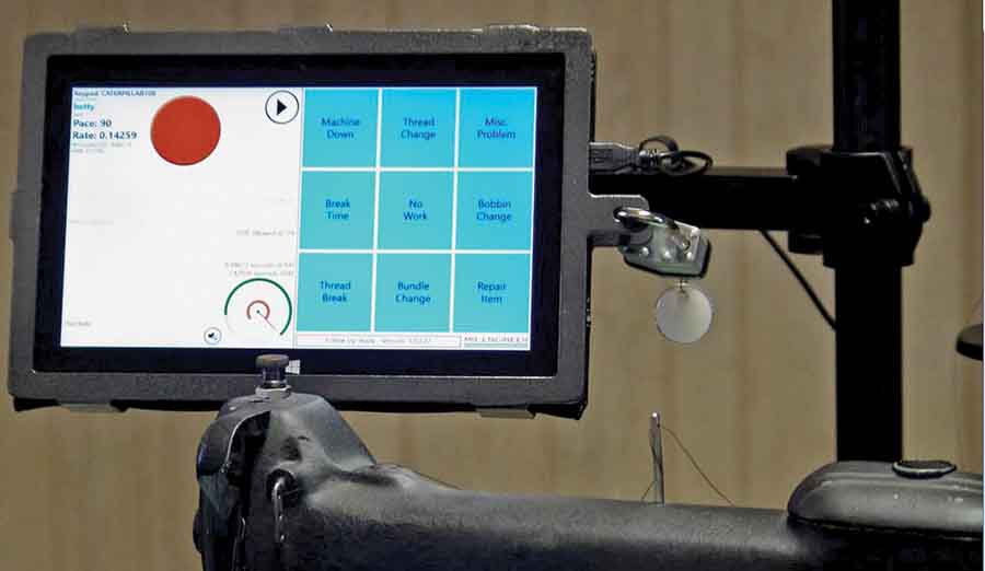
Observing operation live and recording time from analogue or digital stopwatch by time study engineers are subject to manual error. In a videographic option, instead of recording time from live operations, the engineers first capture the operation cycle in video and then observe the video to record the time. Here engineers can record the time at leisure and can rewind any operation, if required. This method ensures perfection, increases speed, reduces subjectivity and easy storage and retrieval of records.
In the traditional time study technique, the important aspect of motion study is being ignored. The latest level of technology involves integrated video imaging using any inexpensive, basic digital video camera, loading the video file in the PC or a Laptop, doing the Video Time Study [VTS] to get the activity description and timing for each activity. The speed of the movie can be adjusted to accurately separate and document the motion elements, the time unit which can be either in seconds or in TMU (time measurement units; 1,00,000 TMU = 1 hour). Another software option is to analyze the multiple still picture wherein the frame interval selection is possible.
 The computerized solution eliminates any need for a stopwatch, clipboard, calculator, charts, paper or pencil in doing a time study. All one needs is portable PC running Windows software. The major advantage is that all calculations are completed instantly, and even partial results can also be observed on-screen as the study is proceeding. It reviews any existing work standard that you have, regardless of whether it was developed from one of today’s predetermined motion time systems (PMTS), from a traditional subjective time study or from historical data.
Requiring no subjective performance rating for a review all one is required to do is to enter a personal, fatigue and delay allowance, and the optional PF&D Wizard™ (Personal Fatique and Delay) will walk you through the process of establishing a new PF&D allowance or updating an old one, even if you’ve never done a time study before. You can take all the results away from the worksite for more extensive analysis. But in most cases, you’ll immediately be able to see and interpret results at the worksite! You can print the results whenever you need hard copy. The optional Database Output feature offers even more capability for analysis.
The IT technology has progressed at a lightning speed during last decade and with the result there are lot of open source software solutions available in the market which can simplify the method study operation analysis. There are video of time and motion study software which not only makes the process 95% faster, but also increases consistency and traceability and improves costing and planning.
Then there are next levels of computerization, where motion analysis software can be used to automatically track and accurately measure the movement of different body parts of sewing operator. Time study application can also be completely deskilled and computerized in a revolutionary method where sewing speed data are directly captured from machine in a non-evasive process. To top it up, the smartphone based time study using android application may become popular among new generation time study engineers.
IE for Floor Layout Improvement
 Amit Anand StitchWorld August 2003
A simple work measurement exercise brings out the reasons for loss of production and a simple work on layout planning can result in better material and man movement thereby increasing efficiency. This type of small improvement is embedded in daily work practice and workers should be empowered to carry out such practices.
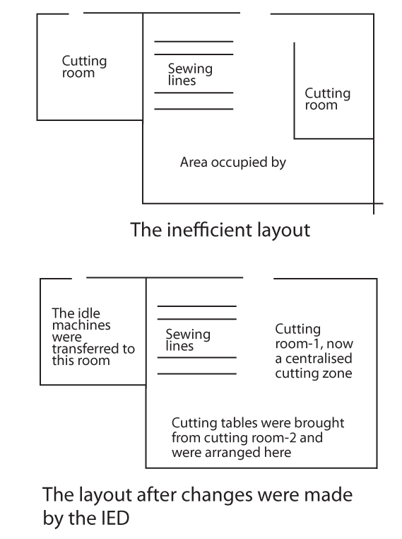
The IE department of ABC Incorporates, examined the layout of the ground floor of the factory and found many faults in its layout.
Adjacent to the cutting room-1 there was another cutting room at a distance of 50 metres. On the other hand there was an area of 20 sq. metres adjacent to the cutting room-1 that was being used to keep idle machines. The practical problems arising out of such layout was that the cutting master had to be on a continuous move from one cutting room to another to oversee the work. And because of this the operators in one of the rooms used to sit idle or while away their time when the supervisor was in the other room. The layout was also resulting in unnecessary movement of fabric and cutting machines. After taking into consideration facts like the total area occupied by idle machines, area occupied by cutting tables kept in the cutting room-2, and the area of the cutting room-2, the IED proposed some small changes in the layout. The changes resulted in better utilization of productive time.
The cutting room was relocated to central production which made it easier for the cutting master to supervise the work. Also there was no need to carry the fabric and cutting machines from one cutting room to another. Such faulty layouts are commonly found in most of the Indian factories and probably it takes an IED to notice these and suggest relevant changes that improve productivity.
Work Measurement Helped Improve Performance
Amit Anand StitchWorld October 2003
What cannot be measured cannot be managed, controlled or improved. Estimation of work is thus the first step in any target setting and/or performance improvement program. Work measurement is the application of techniques designed to establish the time for an average worker to carry out a specified manufacturing task at a defined level of performance. It is concerned with the length of time it takes to complete a work task assigned to a specific job.
A company that has a fully functional IED found a unique way of identifying the impediments in the way of normal production. It was done with an understanding to improve productivity. The modus operandi was to record the targets for each operation on the hourly production card and the moment it is identified that an operator has failed to achieve the target in a particular hour; the supervisor was expected to ask him/her the reasons for it. It was found the operator failed to achieve the target because of:
a) Factory failure like power breakdown, unavailability of cut pieces or accessories, etc.,
b) Slow feeding of pieces from the operation prior to that operation,
c) Machine breakdown, or
d) His inability to do that operation.
Thus, at the end of the day there is a record that informs why in a particular operation the targets could not be achieved; what was the impediment (or the cause that killed the productive time) and based on this the management plans the production for the next day. Thus work measurement helps in comparing, knowing and improving upon the productivity performances within a factory.
Critical Path Method Reduces Work in Progress in a Sewing Line
 Pradeep Jha StitchWorld May 2004
Simple operation research principle of Critical Path Method (CPM) can be judiciously used for reducing WIP and throughput time in progressive bundle unit system of sewing operations. While consultants play a major role in helping the manufacturers improve their bottomline performance, adoption of proven scientific principles still remain elusive to garment manufacturing.
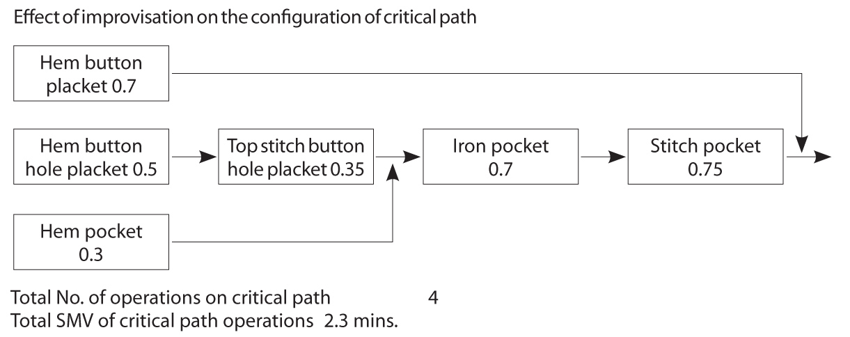
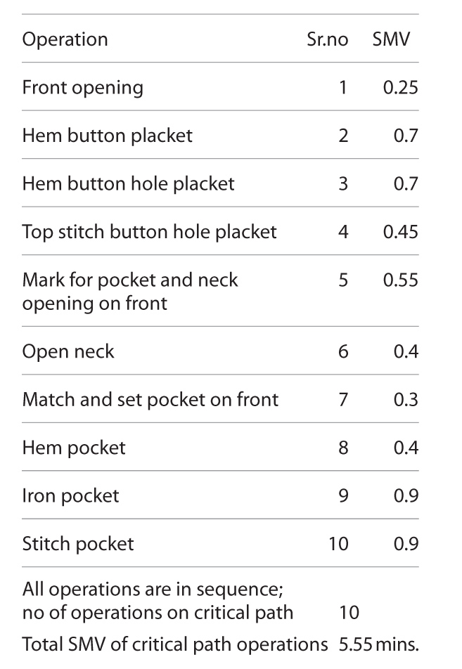 In a typical shirt (checks) manufacturing unit in India, the structure of the front section may be as given below. In such a structure, both the front panels move as a pair. Hence, before each operation, they need to be segregated and after execution of the operation, they need to be paired, bundled and passed to the next operator. In this situation the front bundle consists of all parts of the front, i.e. front block and pocket, and this bundle with all the parts moves across all operations of the front section. This makes conducting any operation on each piece more time consuming and cumbersome for the operator.
Now the same front is produced by following a slightly different procedure, viz. simultaneous parallel processing. In the new procedure the front panels are separated, pocket placements marked and pockets matched in the cutting department only. Further, instead of having one front bundle three bundles and three feeding points in the frontal section are created, each consisting of left panel, right panel and pocket respectively. While operating various pieces in the bundle, it is a must to adhere to sequence discipline; ascending or descending will not make much difference, but consistency does make a difference. Change in sequence order will only create confusion and quality issues.
The above process results in SMV reduction.
Benefit of simultaneous parallel processing is the smaller critical path, which means lesser throughput time for front section, hence quality problems will be identified earlier and also one will get much less number of damaged fronts, therefore rectification of the damage will be faster and reflection of this on the production will be minimal. However, the identification of bottlenecks is easier in the second case, since the front is divided into three small groups. In case of low production, a supervisor can easily trace which section is under-performing and accordingly take corrective action. Even the line balancing is easier in this case because it is easier for supervisor to see which sub-group is under performing and can be supported by an over performing sub-group. Supervisor or production executive easily gets to know the output of each sub-group. With these changes the productivity of the group will be optimum and operators better utilized.
It will also be easier to balance the line as less deviation from pitch time is noticeable in the second case which makes balancing a less difficult task. This was basically the outcome of elimination of helpers from the production floor and their relocation in cutting. When the helper for operations 1,5,6,7 were dedicated for a batch they were substantially underutilized; now with their relocation in cutting they can feed two or more batches and this enhances their individual performance as well as the unit productivity.
 Ergonomics Play Crucial Role in Workplace Design
Suresh Dureja Ravi Vidyanathan StitchWorld September 2003
Workplace ergonomics is an integral part of Industrial Engineering. There are many different ergonomic principles for productivity and efficiency improvement of the operator. Although tangible returns on such initiatives are difficult to accrue in short term, manufacturers have started adopting numerous such initiatives, sometimes for long-term commercial benefits and sometimes for scoring points in compliance parameters.
Industrial engineer plans the workplace in such a way that the operator is provided with maximum ease, minimum displacement and focused operating technique (maximizing needle time).
Poor design of sewing machine systems, besides reducing productivity, can lead to many health problems for the operators. The angle of the head, lower than its natural position cause strain on the neck and shoulder muscles, and may lead to headaches and some cumulative trauma disorders (CTDs). Normally, in the industry the operator is made to pick up parts from greater heights than recommended which can lead to back pain and strain on the shoulder and elbow joints. Repetitive motion caused by the foot pedal can lead to CTDs in the foot. Excessive noise and poor lighting can also lead to hearing and vision problems. The frequency of persistent neck and shoulder injuries increase with years of work and can cause permanent health issue.
Ergonomics in workplace design includes:
- Principles of moving parts of the human body.
- Principles of ranking the extent of movement of finger to shoulder, the smaller the movement the higher the rank.
- Principles of arranging shop floor.
- Principles of designing equipments and tools.
To analyze body part’s motion and posture, risk analysis of such motions, and/or postures available are various software like Peak Motus® (www.peakperform.com), Ergo Master® and ErgoIntelligence® (www.nexgenergo.com), which can be used to study motions and their effective optimization.
Some of the proven work-aids, which affect a lot of ergonomic comfort and greatly contribute to operator performance, are illustrated below. Some of these workaids have been able to cut down the operator fatigue level up to 18%. These work-aids have proven to be widely used throughout the industry effecting savings in material handling reduction and minimum operator displacement. There are no work-aids which fit well under all conditions. They need to be e(r)gineered to suit the purpose.
Give IED a Friendly Face
Amit Anand StitchWorld October 2003
The conflict between IE department and production department persists. Resolving the conflict will increase the contribution and effectiveness of IE in manufacturing in a big way. It’s an undisputed fact that an IED manager needs to be technologically sound, but besides that, he also needs to be an excellent communicator, as he would need to communicate with the line supervisors and operators on the one side and on the other he would be reporting to the top-most management of the company. In nutshell, he should also have a good understanding of human psychology and human behaviour. The primary duty of IED manager is to get the job done, remove all the apprehensions of the workers and give them a better understanding of the entire process of target setting, encourage them to express their doubts and make them understand the process by which the IED set targets (of course, in the simplest and lay man’s terms). He should emphasize the person on whom time study was performed was also human just like them and not a machine and if he can perform an operation in a particular time frame, so can they. He should emphasize that as an operator they have more advantage in the sense that they perform the same operation in the sewing line for a long period of time (as they run large quantity orders) unlike the operator on whom time study was performed. Thus, they have the opportunity of getting more and more perfect with the operation, as their learning curve swells with time and hence they could have not only met the target but even beat it.
Thus IE should revaluate and revise the grade of the operator from time to time and ensure that they get salaries matching to their rating.
The IE manager should also highlight that while setting targets the IED would take a minimum of 10 readings per operation, thus developing a pool of data, so that it could arrive at an average figure and negate any chance of relying on a maximum or minimum value.
They should be properly informed about the type of allowances that was given to them and convince them that all their natural needs will be taken care of while setting targets for them.
Once the targets are set, the IED should coordinate with their production counterparts and find out whether the targets were being achieved on the production floor. Industrial Engineer should try to find out the operations where the targets had remained elusive for the production team and should also try identifying into the factors responsible for it and either change the target or guide them.
The job of IE does not end here, but it is just tip of the iceberg… IE is also responsible to investigate deeply into the reasons for lower production, extending a helping hand in analysing whether the problem is related to men, machine or material.
Industrial Engineers when using PMTS system should be careful and particular about mentioning the workplace, location of components and methods being performed by the operator while setting the target. More often than not same style is being sewn in multiple lines in multiple factories; centralized IE department gives same target for all lines/factories. But either workplace or location of components or both changes due to factory and/or operational constraints which leads to variation of timings. Reasons that lead to variation of methods are the different types of machine layouts, different lighting arrangements, different types of seating of operators, and the likes. The variations of timings create doubts over authenticity of the targets being set by industrial engineers and conflict starts between production and IE department.
Improve Productivity by Overhead Material Handling System
Team StitchWorld StitchWorld January 2008
Studies showed that in garment manufacturing industries, material handling and other associated non-value added activities accounted for 80% of operator’s time, leaving only 20% of the time for adding value and for actually sewing the garment. It became evident that efficiency in the apparel industry could be improved upon by eliminating the highly unproductive material handling procedures. It could be achieved by developing systems to convey garment parts from one workstation to another, in a coordinated manner.
The use of overhead material handling system in sewing enables sewing in hanging condition thus reduces handling time during sewing. The hanger acts like someone is holding the garment component to be sewn at right distance from the needlepoint and at right height from the sewing bed, operator simply concentrates on the sewing area without getting bothered about the rest of the component handling. The system does not waste valuable floor space and required no major modification to the existing machines. The system eliminates ‘bundle handing’ (tying and un-tying of bundles) and allows all the material needed for a specific garment to be transported as a unit directly to the sewing machine of any workstation. The system also ensures crease-free, soil-free transporting of cut parts and half-sewn components amongst sewing stations in a organized transparent manner. Improved transparency reduces the need for more WIP thus lesser throughput time. Study claims that implementation of this reduces the direct labour cost component by 9.7%.
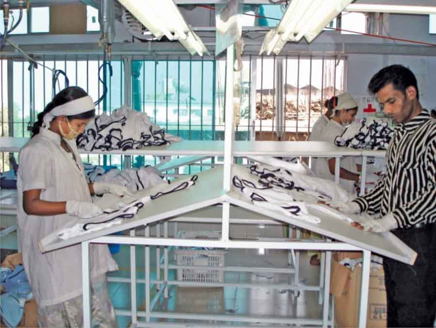
Method Improvement in Finishing Room
Roger Thomas StitchWorld October 2010
Typically, finishing involves post sewing operations like ironing/packing, however there are also several non value added operations such as inspection and corrective operations like thread trimmings, spotting and duplication of process to ensure there is no lapse in quality. At times the garments are examined up to five times, the threads are cut twice and the pressing is done twice. In all, the garments pass through 13 processes before completion.
Standardization of method is not only important in sewing but also in finishing reducing non value added work while maintaining the process quality. Operators who trim the threads should be trained to work methodically to a set pattern so that each garment is handled in exactly the same way, starting at the same point and progressing around the garment in a predetermined sequence to ensure that every part of the garment is processed prior to its completion. Special wire top workplaces are also recommend for thread cutting which allows removed threads to fall into a trough built into the table so that they do not land on the next garment to be trimmed, a bag is fixed to the bottom so that the thread are collected and not deposited on the floor. Similarly inspection also should follow standard method of start and finish.
If a standardized method of eye movement is followed, the time taken for inspecting a defective and a non-defective garment would be approximately same. To eliminate creasing after ironing, the garments should be hung and continue to be worked on from a hanger. This will remove the final pressing process before bagging. Garments can have the odd thread removed on the hanger whilst doing the final check. The measurements should also be confirmed at this time. This process flow serves to eliminate duplication of operations and will dramatically reduce handling of the garments.